The physiscal connectos of the RTU-X depends on the model you use.
In the following, both cases are presented.
¶ DIN Model
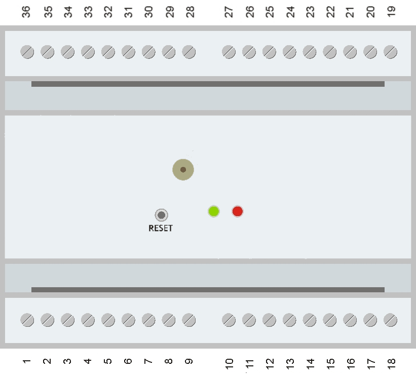
| Borne | Descripción | ||||||
| 1 | VDC / L | ||||||
| 2 | VDC / L | ||||||
| 3 | GND / N | ||||||
| 4 | GND / N | ||||||
| 5 | 12 VDC / 24 VDC output | ||||||
| 6 | GND | ||||||
| 7 | AIN0 / Analog input 0 | ||||||
| 8 | AIN1 / Analog input 1 | ||||||
| 9 | GND | ||||||
| DIN | DOUT | AIN | RS-485 | SDI-12 | EM | ||
| 10 | Expansion 1 | GND | COM | GND | RS485 B | N/C | Voltage in |
| 11 | Expansion 1 | IN 11 | OUT 11 | AIN 5 | RS485 A | Data | Line |
| 12 | Expansion 1 | IN 12 | OUT 12 | AIN 6 | 12 V | 12 V | N/C |
| 13 | Expansion 1 | IN 13 | OUT 13 | AIN 7 | GND | GND | Load |
| 14 | GND | ||||||
| DIN | DOUT | AIN | RS-485 | SDI-12 | EM | ||
| 15 | Expansion 2 | GND | COM | GND | RS485 B | N/C | Voltage in |
| 16 | Expansion 2 | IN 8 | OUT 8 | AIN 2 | RS485 A | Data | Line |
| 17 | Expansion 2 | IN 9 | OUT 9 | AIN 3 | 12 V | 12 V | N/C |
| 18 | Expansion 2 | IN 10 | OUT 10 | AIN 4 | GND | GND | Load |
| 19 | IN7 / Digital input 7 | ||||||
| 20 | IN6 / Digital input 6 | ||||||
| 21 | IN5 / Digital input 5 | ||||||
| 22 | IN4 / Digital input 4 | ||||||
| 23 | IN3 / Digital input 3 | ||||||
| 24 | IN2 / Digital input 2 | ||||||
| 25 | IN1 / Digital input 1 | ||||||
| 26 | IN0 / Digital input 0 | ||||||
| 27 | COMIN / Digital inputs common | ||||||
| 28 | OUT7 / Digital output 7 | ||||||
| 29 | OUT6 / Digital output 6 | ||||||
| 30 | OUT5 / Digital output 5 | ||||||
| 31 | OUT4 / Digital output 4 | ||||||
| 32 | OUT3 / Digital output 3 | ||||||
| 33 | OUT2 / Digital output 2 | ||||||
| 34 | OUT1 / Digital output 1 | ||||||
| 35 | OUT0 / Digital output 0 | ||||||
| 36 | COMOUT / Digital outputs common | ||||||
¶ IP68 Model
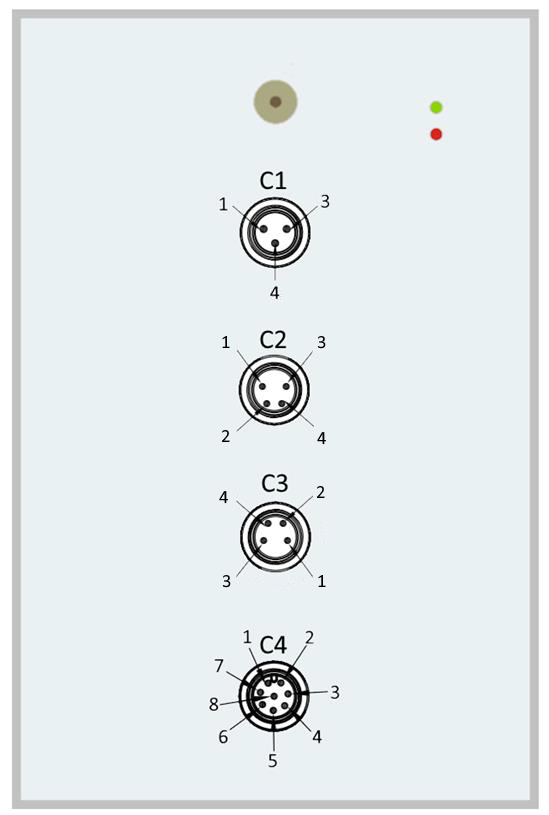
| C1 (Power supply) | ||
|---|---|---|
| Pin | Color | Descripción |
| 1 | Brown | VDC in VDC Model / N in VAC model |
| 3 | Blue | GND in VDC Model / L in VAC model |
| 4 | Black | Do not connect |
| C2 (Expansion 1) | |||||||
|---|---|---|---|---|---|---|---|
| Pin | Color | Expansion module | |||||
| DIN | DOUT | AIN | RS-485 | SDI-12 | EM | ||
| 1 | Brown | IN 10 | OUT 10 | AIN 4 | GND | GND | Load |
| 2 | White | IN 9 | OUT 9 | AIN 3 | 12 V | 12 V | N/C |
| 3 | Blue | GND | COM | GND | RS485 B | N/C | Voltage IN |
| 4 | Black | IN 8 | OUT 8 | AIN 2 | RS485 A | Data | Line |
| C3 (Expansion 2) | |||||||
|---|---|---|---|---|---|---|---|
| Pin | Color | Expansion module | |||||
| DIN | DOUT | AIN | RS-485 | SDI-12 | EM | ||
| 1 | Brown | IN 13 | OUT 13 | AIN 7 | GND | GND | Load |
| 2 | White | IN 12 | OUT 12 | AIN 6 | 12 V | 12 V | N/C |
| 3 | Blue | GND | COM | GND | RS485 B | N/C | Voltage IN |
| 4 | Black | IN 11 | OUT 11 | AIN 5 | RS485 A | Data | Line |
| C4 (I/O) | ||
|---|---|---|
| Pin | Color | Description |
| 1 | White | IN0 / Digital input 0 |
| 2 | Brown | IN1 / Digital input 1 |
| 3 | Green | OUT0 / Digital outtput 0 |
| 4 | Yellow | COMOUT / Digital output common |
| 5 | Grey | AIN1 / Analog input 0 |
| 6 | Pink | AIN0 / Analog input 1 |
| 7 | Blue | 12 VDC / 24 VDC Output |
| 8 | Red | GND |